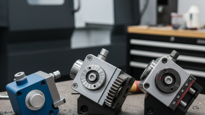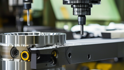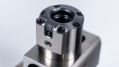
Choosing the right Cnc Mill Boring Head can determine whether a setup produces clean bores or costly rework. In 2026, buyers face many options, from compact manual heads to precision systems designed for demanding production work. The best choice depends on spindle compatibility, adjustment range, rigidity, and actual machining needs.
A reliable boring head should hold its setting under cutting pressure. Look closely at the slide mechanism, graduations, locking method, and stated accuracy. A smooth dial is useful, but it does not prove long-term stability. Check the manufacturer’s technical data, then compare it with independent user experience and workshop testing. Measure the arbor fit carefully. A small mismatch can create visible chatter inside a bore.
Real workshop experience matters. Cast iron, steel, aluminum, and hardened materials place different demands on tool stiffness and adjustment control. A head used for occasional repair work may not need the same precision as one used beside a coordinate measuring machine. That difference is easy to overlook.
Small errors become expensive.
This guide examines leading 2026 models through practical buying criteria, including repeatability, balance, cutter support, and maintenance access. It also considers honest limitations, because no boring head performs perfectly in every machine or material. Some specifications look impressive on paper but feel less convincing after extended use. Readers can use these findings to compare products with greater confidence and avoid paying for features they will rarely use.
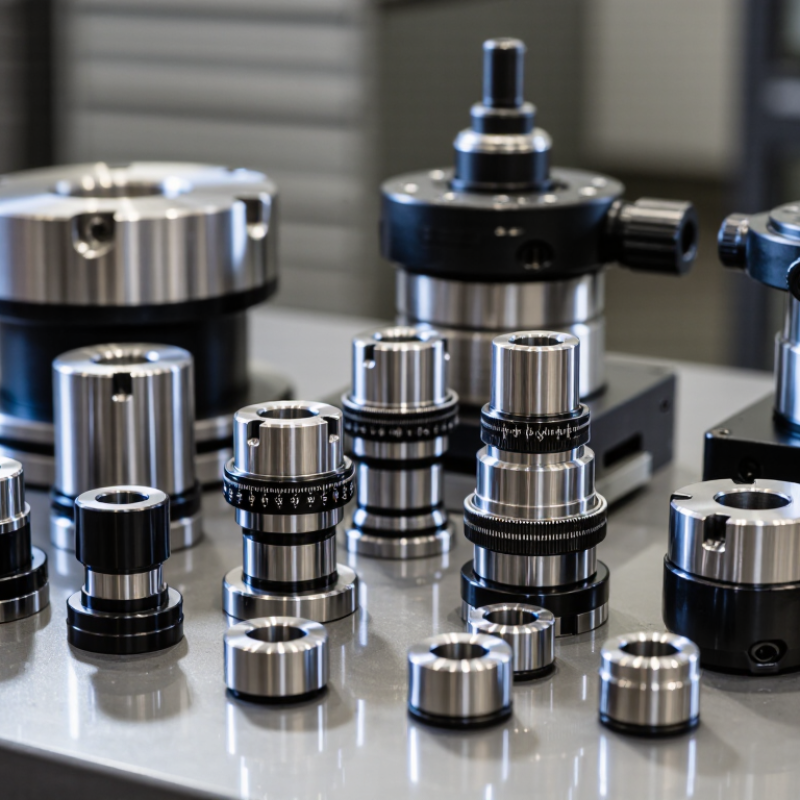
A CNC mill boring head is a precision tool used to enlarge or correct an existing hole. Unlike a fixed boring bar, it allows controlled radial adjustment. The cutter moves outward from the head’s center as the adjustment screw turns. This changes the cutting diameter by a measured amount.
During machining, the CNC spindle rotates the boring head while the feed axis guides it through the workpiece. The boring bar removes a thin, consistent layer from the hole wall. A rigid setup matters. Even small vibration can leave visible chatter marks inside the bore. I have found that checking runout with a dial indicator before cutting prevents many avoidable errors. It takes only a few minutes.
When choosing a boring head for 2026, examine its adjustment resolution, diameter range, shank fit, and load capacity. The head must match the machine spindle and remain secure during deep cuts. A clear scale helps, but it should not replace measurement with a bore gauge. I once trusted the engraved graduations too much, and the final hole was slightly oversized. That mistake changed my setup habits. Use conservative cutting data, confirm tool projection, and measure after each controlled pass. Coolant may improve finish, although excessive flow can hide chips near the cutting edge. Some workpieces also respond unpredictably to heat, so measurement should happen after the part stabilizes.
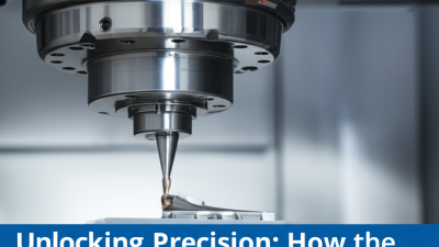
A CNC boring head should be chosen by specification, not appearance. The working diameter range defines whether it suits small holes, large bores, or both. Check the adjustment resolution carefully. Fine settings, such as 0.01 mm, help control final dimensions without removing too much material.
Taper compatibility matters. The head must match the machine spindle and holder system securely. Incorrect taper selection can create vibration, poor surface finish, and dangerous tool movement. Low radial runout is equally important. For precision work, verify the manufacturer’s measured runout and testing method. A rigid body also helps when boring steel or deep holes.
Balance should match the intended spindle speed. An unbalanced head may leave visible marks on the bore wall. Look for secure locking after adjustment, clear diameter markings, and adequate clearance around the workpiece. Coolant access can matter when chips build up inside a deep bore. I once selected a head with a wide range but ignored its limited rigidity. The range looked impressive. The results were not. Smaller adjustments and a stronger locking mechanism would have served that job better.
Consider boring depth, insert geometry, and replacement insert availability. Carbide inserts may suit harder materials, while sharper geometries can improve aluminum finishes. Always compare the head’s maximum speed with your machine’s actual operating range. Specifications are useful, but shop conditions can expose weaknesses that a catalog cannot.
Which boring head specifications matter most for CNC milling?
Typical metric values shown here reflect specification ranges commonly published for general-purpose CNC boring heads. Radial adjustment range determines the usable bore diameter, adjustment resolution affects finishing accuracy, spindle speed limits influence productivity, and tool shank capacity must match the required cutting load. Always verify the exact values for the selected head, arbor, and machine spindle.
2026 Best CNC Mill Boring Head Buying Guide
Comparing boring heads starts with the adjustment system, not the price. Fixed heads suit repeatable work, while adjustable heads handle varied hole sizes. Micrometer-style heads offer finer control than simple slide adjustments. This matters when a bore must hold tight tolerances across steel, cast iron, or aluminum.
Material choice affects stability and service life. Hardened alloy steel resists wear and vibration. Carbide components can improve edge durability, but they cost more and may chip after poor setup. A balanced head with sealed bearings often feels smoother during slow feeds. It should also maintain concentricity after repeated adjustments. Check the maker’s test method. “High precision” means little without measured runout data. ISO 230-2 provides a useful framework for evaluating machine-tool positioning accuracy, although it does not replace a boring-head test.
Tips: Compare radial adjustment range, minimum bore size, maximum boring diameter, and locking strength. Ask for runout readings at several settings, not one perfect sample. Deloitte’s 2023 Global Smart Manufacturing Survey found that 86% of surveyed manufacturers expect smart manufacturing to support competitiveness within five years. That trend favors tools with repeatable settings and traceable inspection data. Still, automation cannot correct a loose arbor or a dull insert. I have seen that mistake. Review spindle compatibility, balance, coolant access, and insert availability before buying. A small digital readout may save setup time, but it can also encourage overconfidence. Test the finished bore with a calibrated gauge.
| Boring Head Type | Typical Diameter Range | Adjustment System | Typical Radial Adjustment | Typical Setting Resolution | Best Application | Main Advantages | Main Limitations |
|---|---|---|---|---|---|---|---|
| Fixed or Conventional Boring Head | Approx. 20–150 mm | Manual slide with locking screws | Usually 0.5–75 mm from center, depending on size | About 0.01–0.05 mm per graduation | General-purpose enlargement of existing holes | Simple construction, broad diameter coverage, comparatively low cost | Manual setting is slower; balance and repeatability depend heavily on operator technique |
| Fine-Adjustment Boring Head | Approx. 10–200 mm | Micrometer screw, worm gear, or differential screw | Commonly 0.25–50 mm from center | About 0.002–0.01 mm per graduation | Precision bores, finishing operations, and close-tolerance fits | High setting control and improved repeatability | Higher purchase cost; excessive cutting force can deflect the slide or damage the adjustment mechanism |
| Digital Boring Head | Approx. 20–150 mm | Mechanical fine adjustment with electronic position display | Typically 0.5–50 mm from center | Display resolution commonly 0.001–0.01 mm | Repeated setups, inspection-sensitive work, and reduced reading errors | Clear metric or inch readings; easier offset calculation | Requires battery or electronic power; display accuracy does not eliminate spindle or tool runout |
| Modular Boring System | Approx. 20–300 mm or more with extensions | Interchangeable cartridges, slides, extensions, and cutting units | Varies by cartridge and configuration | About 0.002–0.02 mm, depending on adjustment unit | Job shops handling many bore diameters and depths | Flexible tooling, reduced duplicate inventory, scalable diameter range | More assembly interfaces can reduce rigidity and increase setup requirements |
| Twin-Cutter or Balanced Boring Head | Approx. 40–300 mm | Opposed cutters or synchronized radial slides | Usually 1–100 mm from center | About 0.005–0.02 mm per setting | Large-diameter roughing and finishing where balance is important | Improved balance, higher material-removal potential, and lower radial imbalance | More complex setup; both cutters must be matched accurately |
| Comparison Dimension | Common Options | Typical Selection Guidance | Why It Matters on a CNC Mill |
|---|---|---|---|
| Body Material | Hardened alloy steel; tool steel; cast iron in some large heads | Choose hardened steel for wear resistance and repeated industrial use; cast iron may provide damping in larger assemblies | Material affects rigidity, vibration behavior, durability, and dimensional stability |
| Slide and Adjustment Components | Hardened steel, alloy steel, carbide contact elements, coated wear surfaces | Look for ground contact surfaces, positive locking, and protected adjustment threads | Low backlash and stable locking are essential for repeatable bore size |
| Toolholder Interface | Steep-taper, modular-taper, cylindrical, or other machine-compatible interfaces | Match the machine spindle interface, gauge length, retention method, and allowable tool mass | An incompatible or poorly balanced interface can cause runout, vibration, or unsafe operation |
| Runout | Fine boring assemblies commonly target approximately 0.005–0.02 mm at the tool, depending on size and setup | Select the lowest verified runout that matches the tolerance requirement | Runout directly influences bore size variation, surface finish, and tool wear |
| Balancing | Unbalanced manual head; factory-balanced head; adjustable counterbalanced head | Use balanced configurations for higher spindle speeds, larger diameters, or long cycle times | Balance reduces vibration, bearing load, noise, and surface-finish problems |
| Locking Method | Clamp screw, wedge lock, gib adjustment, or dual-lock system | Prefer a rigid lock that does not shift the slide during tightening | Poor locking can change the programmed bore diameter during cutting |
| Coolant Capability | External coolant; through-tool coolant; coolant-ready without internal delivery | Verify pressure limits, sealing, outlet position, and chip evacuation requirements | Adequate coolant improves tool life and helps remove chips from deep bores |
| Maximum Recommended Speed | Often approximately 1,000–6,000 rpm, but highly dependent on diameter, balance, and toolholder | Always follow the lowest limit specified for the head, holder, cutter, and machine | Large eccentric tools generate substantial centrifugal force as speed increases |
| Cutting Insert Compatibility | Indexable inserts; brazed tools; solid-carbide boring bars; modular cartridges | Match insert geometry and grade to the workpiece material and required cutting depth | The insert controls cutting force, chip formation, finish, and achievable tolerance |
Selecting a CNC mill boring head starts with the workpiece, not the catalog photograph. Measure the required bore diameter, depth, material, and tolerance. A compact head suits small holes and light finishing cuts. Larger heads provide more adjustment range, but they also increase tool weight and spindle load.
Match the shank and interface to your machine’s spindle. Confirm maximum speed, allowable runout, and clearance around the workholding setup. For steel, choose a rigid body with fine radial adjustment. Aluminum may tolerate higher cutting speeds, but sharp inserts and effective chip evacuation remain important. Deep bores need a suitable extension, although excessive reach can cause vibration and poor surface finish.
Accuracy depends on more than the boring head. Inspect the spindle taper, clean every mating surface, and verify runout with a dial indicator. I once selected a head with generous capacity for a small repair job. It worked, but the extra mass made setup slower and less stable. That mistake changed how I compare tools.
Check adjustment graduations carefully. Smaller increments help when correcting a tight tolerance. Use the manufacturer’s cutting data as a starting point, then adjust for tool overhang, coolant, and machine condition. Test cuts are worthwhile. Even experienced machinists can overlook a worn insert or a slightly damaged taper. Record the final settings for repeat work, but recheck them when the material or fixture changes.
Before buying a CNC mill boring head in 2026, check its spindle interface carefully. The taper, retention method, and gauge line must match your machine. A small mismatch can create vibration, poor surface finish, or dangerous tool movement. Measure the available boring range against your real workpieces. Extra capacity is useful, but oversized heads may reduce clearance and rigidity.
Runout matters more than an impressive adjustment scale. Ask for measured accuracy, not only a printed specification. A dial indicator should confirm the result at the cutting edge. Check the adjustment resolution, locking mechanism, and repeatability after several corrections. Hardened tool materials can improve service life, but heat treatment quality still matters. I once trusted a smooth adjustment knob too quickly. The mechanism felt precise, yet the lock shifted slightly under load.
Tips: Inspect the head with a clean spindle and calibrated gauge. Test it at low and higher speeds, then examine the finish on a trial bore. Check coolant access, balancing information, replacement parts, and technical drawings. Confirm that the boring bars are supported firmly. Keep notes from the test. Small details are easy to forget. A reliable supplier should explain limitations clearly, provide inspection data, and answer questions about stiffness, maintenance, and compatible tooling without vague promises.