Moisture in compressed air can collect in pipes, damage pneumatic tools, and interrupt production. An Auto Drain Water Separator helps remove liquid water before it travels farther through the system. But choosing one involves more than matching a connection size. A separator that looks suitable on a product page may perform poorly if its flow capacity, pressure range, or drain arrangement does not fit the actual installation. Small details matter.
Start with the operating conditions, not the sales description. Check the system’s working pressure, air consumption, pipe size, and expected condensate load. Consider whether the unit will sit near a compressor, inside a humid workshop, or in a location that is difficult to reach. These conditions affect both separation needs and routine maintenance. The seven tips in this guide cover capacity, filtration, automatic drain types, materials, installation, servicing, and supplier documentation. Each factor can influence reliability, but no single specification tells the whole story. Real operating data is sometimes incomplete, and that can make selection less certain. Be ready to verify assumptions against equipment manuals and, where needed, guidance from a qualified compressed-air professional. A careful choice should suit the system today and remain practical to inspect tomorrow.
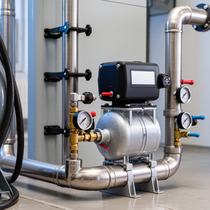
Before selecting an auto drain water separator, define where it will operate. A compressor aftercooler, receiver tank, and point-of-use line can produce different liquid loads. Record the compressor type, operating pressure, inlet temperature, flow rate, and whether demand peaks sharply. Include the wettest expected conditions, not just an average shift. A separator sized only to the nameplate flow may struggle when hot, humid air meets a sudden production surge. Small details matter.
Then specify what “dry enough” means for the equipment downstream. A receiver tank may need reliable bulk-liquid removal; sensitive instruments may also require filtration or a dryer. These are different jobs. ISO 8573-1:2010 classifies compressed-air water content by pressure dew point: Class 2 is at or below −40°C, while Class 4 is at or below +3°C. Those figures describe water vapor quality, not a separator’s liquid-removal efficiency. Keep the distinction clear.
For performance comparisons, ask for test conditions that resemble your actual pressure and flow. ISO 12500-4:2009 provides a test method for evaluating water removal by compressed-air filters, which can help make claims more comparable. Check drain capacity, allowable pressure drop, and behavior during continuous condensate loading. A tidy specification sheet can feel convincing. It may still omit the worst operating hour. Revisit the assumptions after installation, because real condensate loads are rarely perfectly steady.
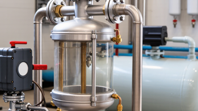
Compare the separator’s rated flow capacity with the air system’s actual demand, not just the compressor’s advertised output. A unit that is too small can restrict airflow during busy cycles. Too large may cost more without improving separation. Check the rating at your operating pressure, since flow figures can change with pressure and test conditions. Read the fine print.
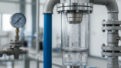
Pressure range matters just as much. Confirm the separator can handle both normal working pressure and likely fluctuations, including startup. Leave a sensible margin rather than choosing a unit that barely meets the stated maximum. A pressure gauge nearby makes changes easier to spot, but it does not replace checking the equipment specifications. This detail is easy to overlook.
Drainage rate should keep pace with the water and oil collected during real operating conditions. In a humid workshop, a small drain may fall behind during long compressor runs. Compare its discharge rate with expected condensate volume, and consider how often the system runs. Check drain connections, too; a kinked or narrow outlet can slow discharge. Test the setup after installation and look for pooling or frequent manual draining. Specifications help, but actual conditions can surprise you.
Automatic drain designs handle condensate differently, so match the mechanism to your compressor room and maintenance routine.
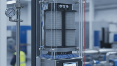
A float-operated drain opens as water collects, without relying on a preset interval. It can suit steady condensate loads, but dirt may interfere with the float and valve. Timer-based drains open at set intervals. They are simple to configure, yet a short opening may leave water behind during humid, heavy-use periods. A longer opening can waste compressed air. Electronic level-sensing drains respond to accumulated liquid and often limit that loss, though sensors and wiring need suitable protection.
Check the failure mode. Can you see a warning if the drain stops working? Look for a manual test button, a clear status indicator, and accessible service parts. Confirm the control voltage and enclosure rating fit the installation area.
A clogged strainer upstream can affect any drain type, so leave room to inspect and clean it. Also consider how the unit behaves after a power interruption; settings may not return as expected. That detail is easy to miss.
Test the drain under real operating conditions, then observe the discharge and listen for unnecessary air release. No control feature replaces routine checks, and the best choice may still need adjustment as condensate loads change.
When choosing an auto drain water separator, check the materials that contact air and condensate. Corrosive moisture can pit unsuitable metal, while oils or cleaning residues may weaken certain seals. Compare the body, bowl, and seal materials with your actual temperature, pressure, and fluid conditions. A clear bowl makes collected water easy to see, but it may need protection from impact and heat. Small details matter.
Service life depends on more than the advertised operating hours. Ask how often the drain valve, seals, and sensing components need inspection or replacement. A float-operated drain may need periodic cleaning; an electronic unit may require checks for blocked outlets or sensor faults. Keep an eye on the drain cycle during routine equipment checks. If it sticks open, compressed air may escape; if it fails shut, water can build up downstream. That trade-off matters. A separator can be correctly sized and still disappoint when its drain is difficult to access. Leave room for inspection, follow the service instructions, and isolate pressure before opening components. In practice, a simple maintenance log can reveal wear patterns, though it will not catch every sudden failure.
Compare materials, service life, and maintenance needs before selecting a unit.
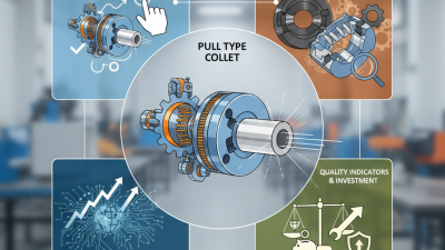
Use these illustrative checklist scores to guide your review, not as measured industry data. Confirm pressure, temperature, discharge capacity, material compatibility, and service requirements against the equipment specifications and your operating conditions.
Tip: Confirm compatibility before comparing prices. Check the separator’s rated pressure, flow capacity, connection size, and materials against your system specifications. Flow can change with demand, so use the actual operating range, not just the compressor’s maximum rating. A unit may fit the pipe and still perform poorly. It is easy to overlook temperature limits, too.
Tip: Plan the installation around the equipment, not just the available space. Follow the manufacturer’s instructions for mounting position and airflow direction. Leave room to inspect the bowl and reach the drain. Support connected pipes so they do not pull on the housing. Route discharge to a suitable collection point; a short, kinked tube can interfere with draining.
Tip: Check safety requirements before installation or maintenance. Identify the system’s isolation points and follow its depressurizing procedure before opening any component. Confirm that the automatic drain cycles correctly during commissioning, and inspect connections for leaks. Keep the area clear of discharged water. One detail may still be missed: review the site’s maintenance procedure and update it for the new separator.
| Selection Tip | What to Check | Why It Matters |
|---|---|---|
| 1. Match the operating pressure | Compare the separator’s rated operating pressure and maximum allowable pressure with the system’s normal and maximum pressures. Check whether the rating applies at the expected operating temperature. | The separator and its drain must be suitable for the pressure they will experience. Use the equipment documentation to confirm the permitted operating limits. |
| 2. Size for the actual airflow | Check the expected flow rate, inlet conditions, and connection size against the separator’s published capacity. Confirm the stated flow rating uses conditions comparable to the system. | An undersized unit can cause excessive pressure drop or inadequate separation. Pipe size alone does not establish flow capacity. |
| 3. Confirm air quality and materials | Verify that the separator is intended for the gas and contaminants in the system. Check wetted materials and seals for compatibility with the fluid, condensate, oils, and expected temperature. | Material incompatibility can lead to deterioration, leakage, or reduced service life. Follow the equipment manufacturer’s compatibility guidance. |
| 4. Check ports and connection details | Confirm inlet and outlet sizes, thread or flange standard, flow direction, and any required adapters. Check the drain outlet size and the connection method for the discharge line. | Matching connection standards helps prevent leaks and avoids unnecessary restrictions or difficult installation changes. |
| 5. Select a suitable automatic drain | Determine whether the drain is float-operated, timer-controlled, or another type. Check its pressure and temperature limits, electrical supply if applicable, discharge capacity, and response to the expected condensate load. | The drain must remove collected liquid reliably under the system’s operating conditions. A timer setting or electrical requirement should suit the installation and maintenance plan. |
| 6. Plan installation and maintenance access | Follow the specified mounting orientation and flow direction. Provide clearance to inspect or service the unit, support connected pipework, and route the drain discharge safely. Install isolation and pressure-relief provisions where required by the system design. | Correct installation supports proper separation and drainage. Accessible components are easier to inspect, clean, and maintain; pipework should not impose undue loads on the separator. |
| 7. Verify safety and condensate handling | Review pressure-system requirements, electrical protection for powered drains, and the site’s condensate disposal rules. Before servicing, isolate and fully depressurize the equipment according to the applicable procedure. | Pressurized components and electrical connections can present hazards. Condensate may contain oil or other contaminants, so it should be collected and disposed of in accordance with local requirements. |
Selection note: Confirm all ratings, installation instructions, and maintenance requirements in the specific equipment documentation and applicable site standards before purchase or installation.