What Are Adjustable Angle Heads and How Do They Work?
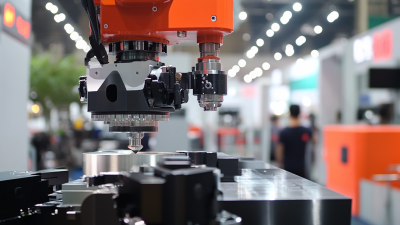
Adjustable Angle Heads let a machining center reach surfaces that a straight spindle cannot approach easily. Inside a crowded fixture, the head redirects the cutting tool toward an angled face, a side wall, or a deep pocket. Its body mounts to the machine spindle; internal gears or a bevel-drive mechanism transmit rotation to the angled output spindle. The operator sets the head’s orientation, secures it, and checks clearance before cutting. Small details matter: tool length, head dimensions, workpiece geometry, and cutting forces can all affect accuracy.
The benefit is practical, not magical. One setup may handle more faces, reducing repositioning and the chance of introducing alignment error. But added reach can also mean less rigidity, more vibration, and tighter limits on speed or torque. ISO 230-1:2012, a reference for testing machine-tool geometric accuracy, underscores why alignment and measurement matter; it is a technical standard, not a market-size report. For broader manufacturing context, the U.S. Bureau of Labor Statistics’ Occupational Outlook Handbook tracks employment trends for metal and plastic machine workers, though it does not isolate angle-head use.
This guide explains how Adjustable Angle Heads work, what their drive components do, and where their limits appear in real machining. A verified, topic-specific expert quotation was not supplied with the source material, so none is attributed here. That omission is deliberate: a polished quote without a checkable source would weaken trust. The engineering question remains concrete: can the head reach the feature while holding the required tolerance?
Definition and Common 90° Configurations of Adjustable Angle Heads
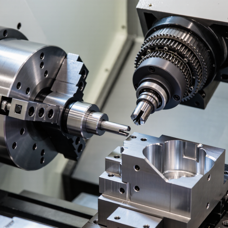
An adjustable angle head is a machine-tool attachment that redirects spindle rotation, letting a cutter reach surfaces the main spindle cannot approach directly. In a common 90° configuration, its output spindle sits perpendicular to the machine spindle. Internal gears transfer rotation through the head. The cutter can then mill a side face, drill a cross-hole, or machine a pocket without repositioning the part. Clearance matters.
Some heads keep the output fixed at 90°. Others let the head swivel or tilt, so the operator can set the cutting direction for angled features. “Adjustable” does not mean every model covers the same range; check the specified travel, locking method, and tool-clearance limits. A setting that looks reachable on screen may collide with a fixture in the machine. Setup checks are still essential. The International Federation of Robotics’ World Robotics 2024 report counted 4.28 million industrial robots operating worldwide in 2023. That figure describes automation, not angle-head use, but highlights why adaptable machining setups matter in modern production cells. Angle heads add access, yet they also add length, weight, and another connection that must be checked for rigidity and runout.
What Are Adjustable Angle Heads and How Do They Work? — Definition and Common 90° Configurations of Adjustable Angle Heads
| Topic |
Configuration or Feature |
How It Works |
Typical Use or Practical Note |
| Definition |
Adjustable angle head |
A machine-tool attachment that redirects rotation from the machine spindle to a tool spindle set at a selected angle. |
It enables machining in directions that may be difficult or impossible to reach with the machine spindle alone. |
| Power transmission |
Right-angle drive |
Internal gearing—commonly bevel gears—transfers rotation between intersecting or angled shafts. The attachment mounts to the machine spindle or tool interface. |
Permitted speed, torque, and cutting load depend on the head design and must be checked against its specifications. |
| Common 90° configuration |
Fixed 90° head |
The output tool axis is perpendicular to the input spindle axis. |
Used for side drilling, tapping, milling, or other operations on a surface that is difficult to access from the spindle’s normal direction. |
| Adjustable 90° configuration |
Indexable or repositionable head |
The head can be set to different angular positions; some designs allow the head orientation to be indexed around the machine spindle axis while retaining a 90° drive angle. |
Useful for reaching different sides of a workpiece. The head is generally positioned and secured before cutting, rather than freely repositioned during machining. |
| Angular range |
Model-dependent adjustment |
“Adjustable” describes the head’s positioning capability, which varies by design. A 90° output angle is common, but not every adjustable head has the same range or adjustment method. |
Confirm the stated adjustment range, locking method, clearance, and permitted cutting positions in the head documentation. |
| Compact-access configuration |
Short-nose or compact 90° head |
A shorter or narrower housing places the cutting tool closer to the mounting interface while maintaining a right-angle output. |
Can help in confined areas, although tool reach, workpiece clearance, and rigidity still need to be assessed. |
| Tooling configuration |
Side-facing cutter or drill |
The tool is held in the output spindle, which points sideways relative to the machine spindle. |
Toolholder type, cutter size, and allowable tool overhang must match the attachment and machining operation. |
| Key operating checks |
Speed, load, and setup |
The gears and bearings carry the cutting load through the attachment. Correct mounting, lubrication where specified, and secure angular positioning help maintain reliable operation. |
Observe rated maximum speed and torque, avoid excessive tool overhang, and verify machine, head, and workpiece clearance before running. |
Core Components: Input Shank, Gear Train, Output Spindle, and Housing
An adjustable angle head redirects rotary power when a straight tool cannot reach the work area. Its input shank connects to the machine spindle and carries rotation into the head. A secure fit helps limit vibration and slipping, so shank size and retention style must match the machine. That fit matters. The gear train transfers motion through meshing gears while changing its direction, often by roughly 90 degrees. Gear quality, lubrication, and alignment affect noise, heat, and service life. A little backlash is normal, but unusual play deserves inspection.
At the other end, the output spindle holds the cutter or tool and delivers the rotation to the workpiece. Its bearings support the load; side pressure beyond the head’s rating can shorten their life. The housing contains and supports these parts, while its adjustable joint sets the working angle. Before cutting, operators should check that the head locks firmly and clears nearby fixtures through its full range. Small details count. In practice, angle markings may not show the exact clearance available around a real part, so a slow test fit can reveal problems a drawing misses. Heat tells a story: rising temperature or changing sound can signal excess load, poor lubrication, or misalignment. These signs are useful, though they do not identify the cause by themselves.
How Bevel Gears Redirect CNC Spindle Power to the Cutting Tool
An adjustable angle head transfers spindle rotation through a compact bevel-gear pair. The driving gear sits on the spindle axis; its teeth mesh with a second gear set at an angle, often 90 degrees. This redirects power toward a side-facing cutter, letting a CNC machine reach surfaces that a straight spindle cannot approach easily. The head’s adjustable body sets the cutting direction, while the bevel gears carry rotation inside. A changed gear ratio can trade speed for torque.
Small losses matter. The U.S. Department of Energy’s Improving Motor and Drive System Performance sourcebook places efficient gear drives broadly in the 95–98% range, though actual results vary with design, lubrication, load, and wear. That figure is a useful benchmark, not a guarantee for every angle head. In use, technicians check gear contact, bearing preload, and lubrication; a dry or poorly aligned mesh can produce heat, noise, and finish marks. Backlash also matters during direction changes. It is easy to overlook. A head that feels rigid by hand may still deflect under cutting force, so tool reach and cutting load should guide setup. Bevel gears redirect power neatly, but they do not erase the limits of the spindle, bearings, or workholding.
How Gear Ratio, Maximum RPM, Torque, and Runout Define Performance
An adjustable angle head redirects spindle power where a straight tool cannot reach, but its ratings matter more than its compact shape. Gear ratio sets the relationship between input and output speed. A 2:1 reduction roughly halves output RPM while increasing available torque, minus transmission losses. That tradeoff can help with larger cutters or tougher materials. Not magic. Check whether the maximum RPM applies at the head’s output, not just the machine spindle. Continuous operation may require a lower speed because gears and bearings generate heat. Listen for changes in pitch, and stop if the housing becomes unusually warm.
Torque capacity should match the cut, tool, and head’s duty cycle; a high number alone proves little. Excess load can cause chatter, deflection, or premature wear, especially with a long extension. Runout describes how far the tool tip wanders as it rotates. Even small runout can enlarge a hole, roughen an edge, or shorten a small end mill’s life. Measure with a dial indicator near the cutting end, using the holder and setup you plan to run. Measure it cold. Keep the head rigidly mounted and minimize tool stickout. A specification sheet is only a starting point: mounting, tool length, lubrication, and machine condition all affect actual results. That part is easy to overlook.
What Are Adjustable Angle Heads and How Do They Work?
How Gear Ratio, Maximum RPM, Torque, and Runout Define Performance
How to read the chart: An adjustable angle head redirects spindle rotation so a tool can reach angled or confined areas. The bars show calculated output speed and torque for a fixed 6,000 RPM, 1 N·m input, assuming a 90% mechanical efficiency. Ratios are input-to-output reduction ratios; actual results depend on the head and operating conditions.
Performance considerations: A reduction ratio lowers output speed and increases torque. The head’s rated maximum RPM is a separate limit and must not be exceeded. Runout is the variation in the rotating tool’s position, commonly measured as total indicator reading; lower runout generally supports more accurate machining. Check manufacturer specifications for maximum RPM, torque capacity, and runout before use.
Mounting Standards: ISO 7388-1, ISO 12164 (HSK), and BT Interfaces
Adjustable angle heads let a cutting tool approach a workpiece from a set direction while the machine spindle remains in its usual orientation. Their mounting interface connects the head to the machine, so matching the standard is essential. A familiar-looking taper is not enough.
ISO 7388-1 describes a steep-taper interface with a flange and retention features. BT holders also use a steep taper, but follow a different interface specification; dimensions and retention details can vary. Do not treat BT and ISO 7388-1 as interchangeable. HSK interfaces, covered by ISO 12164, use a hollow, short taper and contact at both the taper and spindle face. That dual contact can support rigidity at high speeds, when the head and machine are designed for it. A clean fit matters.
Check the machine-side interface, retention method, permissible speed, and head manufacturer’s compatibility data before installation. Also consider the head’s added length and mass. These affect clearance, balance, and cutting loads. It is tempting to focus only on the angle range. That can miss the practical issue: a head may mount correctly but still exceed the machine’s limits. Verify the exact interface drawing. A careful measurement at the spindle nose can prevent a costly mismatch.